In the meantime, I finished up my Kaleidoscope Goggles... and they are SO COOL! (To a geek, obviously... not sure what the rest of the world will think.) The kids at my basic electronics camp next week should find them very eye-catching. The soldering and programming will be a bit beyond most or all of them I imagine, but my plan is to show them a bunch of electronic gizmos and gadgets to inspire them to learn as much as possible during the week AND to continue learning when the camp is over.
 |
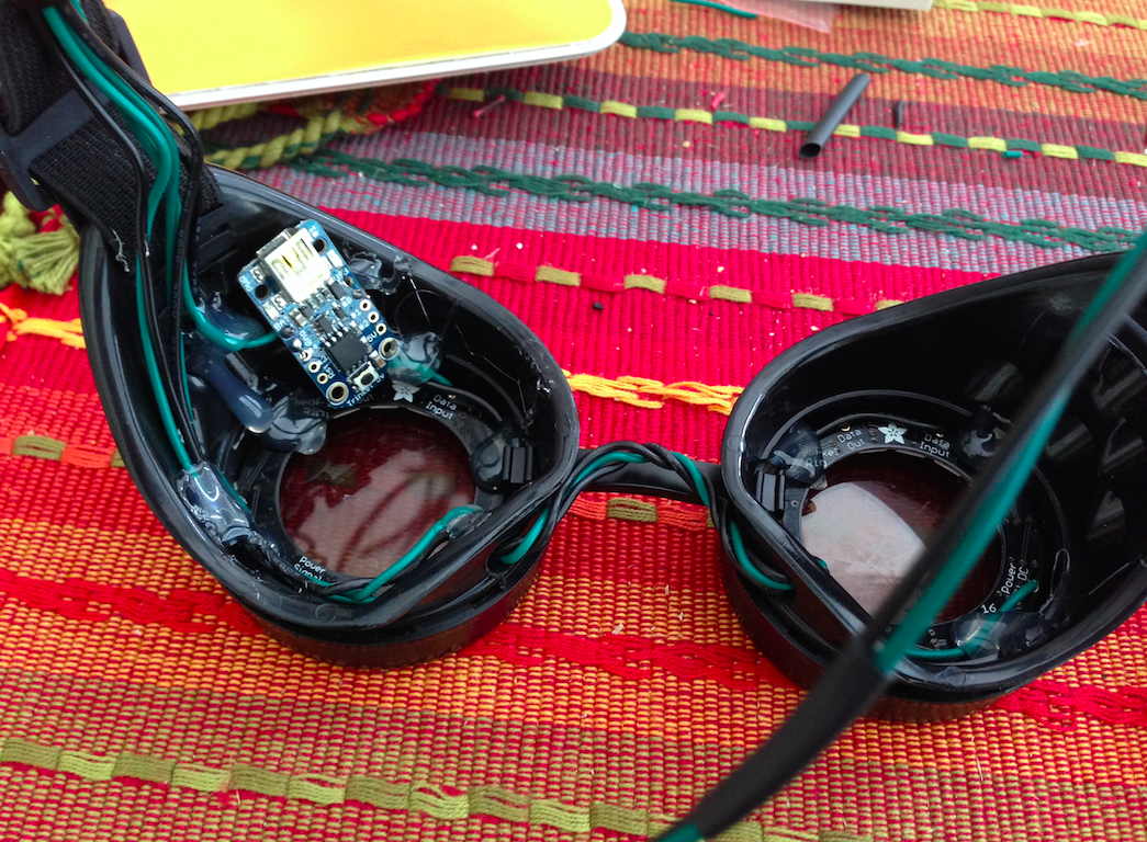
| Putting the first NeoPixel ring into the goggles. |
The controller for this little gizmo is the Trinket device. It operates in a similar manner to an Arduino -- you even plug in a mini-USB cable to upload programs to it. I'll tell you right now... I got into trouble getting this thing setup initially, but Adafruit's forums help set me straight. If you follow the instructions verbatim (here), you'll most likely find yourself trying to install something called AVRDude and configuring various files. FORGET IT! When the instructions just tell you to read the Trinket Tutorial, do NOT go down that AVRDude installation and configuration route. Just install the all-in-one package and then move straight to the Arduino IDE installation. I did do the manual configuration to add the Trinket files after I'd installed the Arduino IDE, but you don't even have to do that apparently. Just get the Arduino IDE talking to the Trinket and then upload the Blink sketch (program) and make sure the red LED light blinks on and off continuously. If it does, you're good to go with wiring up the entire thing to test before putting in the goggles.
 |
| The solid core wires makes it easy to follow a curve. |
After ensuring all components worked, I drill two holes in the black plastic goggles (also purchased from Adafruit). I drilled these where your nose would be located if you were actually wearing the goggles. These are NOT to be worn over the eyes, but instead over the eyebrows. They're just for show... do NOT put these LEDs anywhere near your eyeballs.
I don't know what kind of wire the Adafruit team was using, but I chose two colors -- black and green -- at either 20 or 18 gauge solid core, not braided. I did this because I like how solid core wire holds its shape when you bend it. I felt this would be useful when running the wires around the inside curves of the goggles, and I was right! Completely easy to carefully route them around the curves and through the two drilled holes.
 |
| Soldering up the second NeoPixel ring. |
I stripped the wires that would be soldered to the rings and the Trinket to about 1/16" -- maybe a little longer. A tiny bead of solder for each wire and the rings and the Trinket had all their wires connected and ready for the circuit to be closed. BUT... before I did that, I stripped all the wires -- a 5V and GND from both rings and a 5V and GND from the Trinket... six wires in all! These went into a breadboard and jumper wires helped connect them to their respective 5V or GND. I turned on the power and verified I had animation. Once that was confirmed, it was time to route the wires out of the goggles, behind the elastic band, and to the small 3xAAA battery box.
 |
| Hot glue holds rings and Trinket in place. |
I used three thin black zip ties to create loops for the six wires (two each from the rings and the Trinket) to feed to the middle of the elastic band and then soldered to the two wires from the battery box that will hang on a string around my neck and hidden from view. I was VERY liberal with shrink tubing. Every 2-3" I'd put on a 1/2" length of black shrink tubing on the two longer wires going down to the battery box.
 |
| All finished! |
The only thing that is left is to clean the lenses of hot glue and add either some vellum paper over the lenses to soften the LED shine... there's a glass shop near my house that I might pay a visit to see if they can just create me two 50mm frosted glass lenses that can be inserted by themselves to replace the two-layer glass pieces that come in the lenses. (The goggle lenses unscrew from the front, so it's easy to pull out the glass.)
I'm quite happy with the final results as you can see in the video below... any questions, just ask.
Up next... revisiting Experiment 2!
Hi,
ReplyDeleteI wonder why did you go for the Trinket, and not for something like this? “Pro Mini Module Atmega328 5v 16M For Arduino Compatible"
http://www.ebay.com/itm/141049209300?ssPageName=STRK:MEWNX:IT&_trksid=p3984.m1439.l2649
That little device might just work, and at almost $4 plus free shipping, it's impressive. The reason I chose the Trinket was basically because I was already ordering the NeoPixel rings from Adafruit and the instructions were already written for the Trinket. The Trinket cost a bit more, but the instructions made it so easy to finish the project and I was already paying for shipping for the rings and goggles. I like eBay for some things, but only when I can group order together like I did with the two gauges.
ReplyDelete