Thursday, August 28, 2014

Experiment 13 Part 2 (Chapter 13) -- Making Mistakes

I'm going to wrap up Chapter 13 with a couple of videos and some photos. Unfortunately, one of the videos you might be expecting is NOT here. I synched my phone and downloaded photos and videos, but the video for the circuit shown in Figure 13-7 (page 96) has disappeared. Poof. It's frustrating because although it wasn't a tricky circuit to wire up, it did take some time. My wiring wasn't as pretty as Charles' (no big surprise), but the circuit did work -- a suitable level of volume (tapping on the electret) got the 555 timer chip started and the 3" loudspeaker to making an awful noise. It would definitely make someone stop talking loud, but I'd probably prefer a higher voice volume than the pitch coming out of that speaker.

Where are you, video!??
Here's a photo of the missing video's circuit. I didn't vary much from Charles' diagram with but a few exceptions -- instead of the 33K (near the bottom of the schematic) I used a 47K... no 33K in my batch and I didn't feel it would be detrimental to the circuit to avoid putting two 15Ks in series. Also, I didn't have a 0.068microfarad capacitor, so I substituted a 0.1microfarad. Again, the circuit worked, so these substitutions didn't seem to have a negative effect.

You can't see the speaker, but you can see the two wires exiting the bottom of the breadboard... it's about a three foot length of wire. Lots of popping and static, but it worked.

Note to self: Find a small baggie of mixed capacitors in all values and buy it! I have a good assortment, but I continue to find values I don't have in my capacitor collection.

After completing the larger circuit, I went back a few pages to a small experiment Charles described that uses two 2N2222 transistors and a handful of 1K and 10K resistors. Depending on the wiring of these resistors, you'll gain a better understanding of the subject of Emitter Follower that Charles introduces on page 94. Voltage at the Emitter (E) is directly related to the voltage at the Base (B). It took me a few reads and then performing the experiment with a meter to grasp what was happening, but it does follow the most basic understanding of a 2N2222... and it pulls in the concept of voltage division once again. Very cool!

Note: You can perform these experiments with a single 2N2222 but it goes faster if you have a pair. Even better, if you have four 2N2222s, wire them up following Figures 13-5 and 13-6 and knock all four tests out on one breadboard.

The chapter does round out with a discussion on some of the problems that Charles encountered with his circuit. I was providing a solid 9V using an AC Adapter with a selector for voltage... whereas it appears that Charles was using a 9V battery more often. Some of the technical issues he encountered seem to be related to that fact. If you're using a 9V battery, definitely read some of the suggestions (on page 98) for fixing the circuit if you're having issues with it.

Up next? Experiment 14! Videos below... Part 1 at top, Part 2 on bottom.


Monday, August 25, 2014

Off-Topic: Lasers!

My apologies for delays in getting new posts up, but I've had a few work-related items drop in my lap as well as a special project come up where I couldn't say no.  I write non-fiction (technology) books for a living, and part of that requires me to create proposals for new books. I'm "down" right now -- meaning I have no books to write. I usually try to be finishing a book as I'm starting a new one, but that doesn't always work out. Last week I was working on a new book proposal that required a LOT of my time...


The other item that stole my time last week was a chance to assemble a laser cutter. Two, actually. I traveled to my parents' house to meet a good friend of mine, Patrick Hood-Daniel. Patrick owns BuildYourCNC.com, where he sells DIY CNC machines, 3D printers, and... laser cutters. Patrick and I wrote a book together years ago called Build Your Own CNC Machine and then followed it up with a Build Your Own 3D Printer book. Patrick has since designed a new laser cutter called BlackTooth, and he came to Florida to help my dad and I each build our own laser cutter. It was a good learning experience as well as a great time to catch up and visit.


Building a laser cutter was definitely interesting. The shell of the laser cutter is made of MDO (medium density overlay), and while it looks like wood, it's resistant to moisture and it resists burning (flare-ups after the material is cut by the laser are unlikely to set it on fire). This is a 40W, so not super powerful -- it can cut 1/4" plywood but slowly. It's got an exhaust fan where I'll be able to vent the fumes from cutting plastics/acrylics.  A water pump circulates water to cool the laser and a small air pump blows air out at the point of the cut to further help prevent flare-ups. This one works like a CNC machine, with two motors controlling X and Y axes... there is no Z axis, however, since the laser controls depth of cut by modifying the power to the laser as well as the time the laser is turned on.

Wiring it up was tricky... and not tricky. It follows a fairly straight forward path, with a power supply providing power to both motors and the laser as well as the fan and water and air pumps. Tubes and wires have to be carefully routed because you've got moving parts inside, and that's where Patrick's help was invaluable. A lot of people have built this laser cutter all on their own, but I have to admit it was nice having the designer there to double-check everything.

Anywa... I'm back in Atlanta now, so I'll be trying to catch up this week on some new posts now that I've got the proposal completed AND the laser cutters assembled.


Monday, August 18, 2014

Experiment 13 Part 1 (Chapter 13) -- Noisy Circuit

I'm breaking Experiment 13 into parts... and there's no video for this first part, sorry to say. The first half of this experiment involved replacing some of the components in the Experiment 12 circuit, namely the 100K resistor with a 1M potentiometer and the 10k pot with a flat 10k resistor. I left the 10k pot in and just cranked it to its maximum value (and checked it with my meter). The 1M pot allows for some tweaking, but I found in my experiments I had to dial it down quite a bit to the lower range (around 200-230k).

Before diving into the experiment, however, I want to address one of the goals of this chapter -- designing a circuit. Charles opens the chapter with an example description of the final circuit (an alarm will sound if the input -- your voice or other noise -- exceeds a threshold) and then proceeds to ask the question - how do you go about designing a circuit knowing the end result you desire?

The key statement IMO is "so long as a circuit can be broken down into sections, and you can make them communicate reliably with each other, and you can test them one at a time, the design process doesn't have to be too difficult."

I've built a few circuits over the past few years where I stole a piece from here and another piece from there... I wasn't designing the schematic and circuit from scratch, but instead using pre-existing circuits that I understood. And that's what's going on here... Charles is pulling bits and pieces from earlier experiments to create one final circuit... and it's pretty slick and easy to follow if you take your time.

For the first part, I just wanted to recreate the input half of the circuit -- the electret must receive input and an increase in voltage needed to be detected from the LM741 with a meter. Figure 13.1 provides four different locations in the circuit to take some readings... I'm including my results below:


These values won't mean much to you if you haven't read pages 91-93 in the book. The takeaway was to notice an increase in the input voltage reading (AC)...  my tapping on the electret with a specific metal pen (voice wouldn't cut it) was providing 0.004V (40mV) and the LM741 was outputing 2.1V at Point C in the circuit (and AC voltage -- remember, the op-amp outputs AC). Point D in the circuit, however, is where the second half of the experiment will continue, and it needed to be at least 2.5V (AC) to trigger the eventual 2N2222 transistor that will be added (in Part 2 of my Experiment 12 post).  I was getting 2.6... so everything is good.

One troubling part to me is the sensitivity of the electret. My voice just doesn't trigger it... even when I'm speaking right into it. Only tapping on the shell with metal pen would get me the upper voltage I needed. I had to practice a bit to get a consistent tap strength, too.

But... it works. I'm getting over 2.5V at point D in the circuit (referencing Figure 13.1) and am now ready to move on to the next half of the circuit...


Wednesday, August 13, 2014

Experiment 12 (Chapter 12) -

Preamp and poweramp... both are found in the simple circuit for Experiment 12. I actually had an LM386 in my collection of parts, but it had a mangled pin. Thankfully this is a fairly common component, and Radio Shack sells them for $2.00... so no waiting.

The experiment does explain how to bump up the gain from the basic 20:1 to 200:1, but I'm going to stay with the default setting for now. If anyone attempts the upgrade and has a video, let me know and I'll be happy to share here with an update.

For my circuit, I did have to make just three modifications. Obtaining two matching 68k resistors was easy (for the middle voltage), but I didn't have a .68 microfarad... in goes a 105 or 1microfarad. I had to substitute a .1 for the .047 microfarad, and I took Charles' advice to add a very large capacitor between + and GND... a 1000microfarad... that helped cut the noise substantially!

I did have the 10microfarad capacitors (x2) and the 330microfarad. After adding in the electret and the 50ohm speaker, you can see my final circuit below.


Initial tests were horrible... lots of static and hissing. Only after replacing the wires to the speaker with a 3' length of braided wire did I get some great results as you'll see in the video. The troubleshooting section is valuable... if you're having static and popping, there's probably a fix.


Friday, August 1, 2014

Experiment 11 Part 3 Final (Chapter 11) -- Data Data Data

I really enjoyed this last part of Chapter 11, but not initially. Remember back from an earlier post that I had mentioned using a 1k trimmer in place of the 5k? Well, I switched it out to a 10K so I could at least mirror the values I was seeing in Charles' data... and then I began running the final phases that start on Page 78. And my data wasn't making any sense! (At least at the time... now I think it might actually make sense once I figured out a very important step that I overlooked... more on that in a moment.)

So, back to the start. I couldn't find a small 5k trimmer like the one used by Charles and I wasn't willing to wait a few days to order one. So, I dug and dug and found an old-style dial-type potentiometer and used jumper wires to wire it into the circuit. This turned out to be a good decision as I was able to dial in more accurate resistances than with a screwdriver on the tiny tiny 10k trimmer.


My first (failed?) test with the 10k trimmer was tracked in my Maker's Notebook with a pen. For the updated test with the new 5k, I switched to an Excel spreadsheet so I could let it do the calculations for me. What was great was that my data was coming in pretty close to Charles' data seen in the chart on page 78. My "op-amp output relative to A voltage divider" data was looking matching up closely.

Now, here's where I think I made my initial mistake. This last part of Chapter 11 is broken into four phases, and I felt good about my results (for the 10k) for Phase 1, but in Phase 2 you start calculating some specific voltage values and such... and on Step 7 is where I got in trouble. My values for Vi (Voltage Differential) were not only larger than Charles' values, but they were flipped. I was getting negative values for the third column (for those of you following along in the book and the chart on page 78) where Charles had positive values and vice-versa. Needless to say, this will most definitely affect the line graph you'll be making for Phase 3. I scrapped it all at that point, figuring I'd done something wrong... and then went on the hunt for the 5k potentiometer. (I'm getting to my error... just stay with me a bit longer.)


Okay, with the 5k, I was able to increment the potentiometer in 250 ohm steps... dialing in was easy with the larger dial on the 5k. (Because I was originally using the 10k, I made my jumps in 1000ohm steps instead of the 250ohm Charles used.)

Phase 1 will have you setting the potentiometer to a variety of values between 1500 and 3750ohms in 250 ohm increments. This means you'll be making 10 readings of the Op-am output voltage (relative to point A in Figure 11.4). The data I collected is shown below:


This concluded the data collection for Phase 1.

For Phase 2, I needed to take measurements of the full resistance offered by the 5k pot as well as the two matching 100k resistors that would be labeled Rl and Rr (left and right, respectively, depending on their position relative to the 5k's connections on the breadboard). I also needed to take the full voltage available from my power supply -- Vcc = 9190 millivolts.

Carefully read and understand how the R1 and R2 values are calculated for the circuit. It all hangs on the resistance dialed in to the 5K plus the full values of the Rl and Rr resistors. The equations for R1 and R2 can be found on page 80, and here's the data from my spreadsheet for those two values with respect to the dialed in resistance of the 5k:


Using R1 and R2 values along with Vcc, Step 6 will have you calculating Vm (voltage at center of voltage divider) using another formula on page 80. Here's my updated spreadsheet with that value:


Finally, to move on to Phase 3 and the required graphs, you need to calculate what's called the Voltage Differential, and this is where I got into trouble on my first run with the 10k potentiometer. The formula is fairly straightforward, and I just created it in the spreadsheet and got the following values:


Comparing my data to the third column on page 78, my data appeared reversed. The +45 and -55 extreme values were close enough to Charles' data that I figured I'd just done something wrong in my calculations... but all the spreadsheet formulas were good after a few double-checks. So what gives?

I re-read Step 7 for Phase 2 and there it was -- "Just divide Vcc by 2, then subtract Vm, and that's the difference between he two inputs. It is properly called the voltage differential, and should be a negative number, so remember to include the minus sign."

Derp. Multiplying all the results in column F by -1 fixed the issue. This isn't an error in the book, but just a misunderstanding in viewing the data. Some of my values WERE negative in value, so I figured  only those negative values were related to the voltage differential. Wrong. (What's probably needed is simply putting a -1* in front of the Vi equation.)

After figuring that issue out, my 10k data maybe DOES make sense. But at this point I was deep enough into the 5k test to keep going. Below you'll find my final spreadsheet:


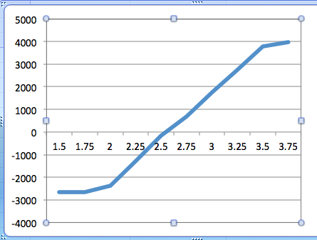
Now on to Phase 3 and graphing the data. Page 81 shows two different graphs. One is taking the first column for horizontal and second column for vertical. The other graph uses first column against sixth column (F in my image above). Here's what I came up with...


Pretty close to straight lines, huh? The first graph has those irregular ends but most of the line does follow a fairly straight path, so I'm going to run with it... Charles also strips out only the straight portion of his data.

Now to calculate the gain for Phase 4. I'll use from 2 volts to 3.5 volts as my two sections to use for calculating the slope.

Slope = rise over run or V / H. Because both charts are using the 1.5 to 3.75 volts range for the horizontal, the runs for both graphs will cancel out, leaving me Gain = V1/V2.

V1 = 6149 (3770 + 2379)
V2 = 67.6 (44.59+22.97)

Gain = 6149 / 67.6 = 91.05

Let's just round that to 90. Hey, that matches what Charles' got! Be sure to read the section on page 82 and understand how Charles checked his math with the original resistor values! The theoretical Gain should be about 100, but hey... I'll take 90! Remember... components aren't always exactly what you measure!

Finally grasping how this little circuit works is a good feeling. It also made the final section in Chapter 11 more enjoyable as Charles explains these very simple op-amp circuit schematics that all of a sudden just make sense.

Closing out Chapter 11, Figure 11-15 is just cool. A voltage split using a 9V battery. I've often wondered how folks made those little 9V battery-powered amplifiers for headphone jacks and such, and now I know. And understand! I even have all the components to make one if I should choose to do so.

Up next is Chapter 12, but that's going to have to wait a week. As I stated in an earlier post, I'll be taking next week off to spend with my two boys before they start school. If I find time in the evenings to tackle Experiment 12, I'll do it... but probably not :)

Back soon...