If you've read and/or worked your way through Make: Electronics, then you'll probably remember how well the 555 timer chip was covered. That said, it's been a few years since I really dug deep into the chip. I went ahead and re-read Chapter 4 that covers the 555, and I highly recommend it -- you'll be reminded of things about the 555 such as:
* pin numbers on chips start from top-left and go counter-clockwise
* dimple/dot/notch goes at the top
* you can read the pulses by measuring voltage from pin 4 and GND
* negative voltage is always applied to pin 1, positive voltage to pin 8
* 555 is triggered by a drop in voltage on pin 2
* 555 output (pin 3) emits pulse when trigger drops below 1/3 voltage value
* when pin 4 is grounded, output (pin 3) shuts off immediately
To reacquaint myself with the 555 behaviors, I wired up a circuit like the one in Figure 4-3 (page 23) and selected some capacitors and resistors that would give me a somewhat easy to monitor pulse length. Referring back to page 157 of Make: Electronics, there's a chart that provides both resistor values and capacitor values so you can fine tune the pulse length you desire. I chose 10 microfarad capacitor for pin 6 (R1) and 470k resistor for pin 7 (C1) on page 23 for an approximate pulse length of 5.2 seconds. The text tells you to use a 0.1 microfarad capacitor between pin 5 and GND. I put an LED into the mix along with a small On/Off button. To the right is a photo of my setup.
The video will show the circuit in action, but let me tell you what I'm doing in the video that's a bit hard to see. I don't have a simple pushbutton handy, so I'm toggling a SPDT switch on and off with my finger. When it's turned on, the LED lights up. But once I start applying power, I begin counting... 1, 2, 3, 4, 5, 6... somewhere between 1 and 5, I turn off the switch. No matter when in the count I turn off power, the LED will stay lit until somewhere between 5 and 6 seconds. Even a quick flick on and off of the switch will keep the LED lit for the full count. That's the pulse length. My counting isn't perfect, but I am getting a pulse length of around 5 seconds that matches the resistor and capacitor values I picked for R1 and C1. Cool!
Last week, I had the opportunity to host a camp for 21 kids, ages 8 to 12. The camp was called Beginning Electronics and Robot Building... or BERB. To say it was a success is an understatement. It was a great group of kids who all wanted to be there to learn some new skills and have a few new experiences.
I worked for almost six months on the camp's itinerary and, of course, immediately tossed about 25% of it out the window once camp began to roll on Monday morning. Honestly, I had just too much planned, and even with two assistants, we had our hands full making sure every camper was on equal footing. (Next summer, I'm cutting the camp down to a maximum of 16 campers.) So, what did we do and learn?
My goal with the camp wasn't to send home 21 new electronics experts and robot gurus... all I wanted to do was plant a seed. I wanted the campers to just get a glimpse of what a more in-depth knowledge of electronics and robots could provide, and I think I succeeded. Throughout the week-long camp, I constantly introduced the kids to small gizmos and gadgets, let them examine them, and tried to explain how they worked (staying within their working knowledge of batteries, voltage, etc.) They loved the Kaleidoscope Goggles, and some small LED kits (such as a POV - Persistence of Vision -- kit) and my Arcade Control... but what REALLY won them over was my 3D Printer... more on that in a moment.
Launching rockets with a 9V and wire.
So, what did we do during the week? We built rockets. Yeah, rockets. Why? Because to launch them, we had to create a closed circuit with a 9V battery. My goal was originally to have them solder up a small hand-made launcher on perf board, but that went out the window when we were pushed for time... goggles on, fifty feet of wire, and a 9V battery and he had 21 successful launches. Not 21 successful landings -- I gave the kids the opportunity to glue on the rocket tip so they'd get a nice big bang... about half chose the destructive route. (It was also about 95 degrees on the baseball field where we launched... HOT day!)
Campers also each got a soldering iron and some solder and anti-solder wick, and we practiced soldering solid core wire to perf board. Out of 21 kids, only two got burned (on their fingers). Not bad! And the two that got burned weren't all that upset and understood their mistake. The campers also got to solder up their Blinky Pins from the MakerShed. That said, I think I'm going to reduce the amount of time we spend on soldering in future camps and increase the hands-on activities that are less risky.
The robot each camper built (and took home) was an Arduino-based robot that consisted of two motors, a battery pack, and a bunch of jumper wire inserted into a breadboard. They really got some experience using a breadboard, and enjoyed building their own robots. Again, don't think they're going home as Arduino experts, but they got just enough hands-on combined with my explanations of components and such that those who really want to dig deeper will feel confident to do so.
Twenty-one robots... all working!
I've been asked to teach the camp again in four weeks. Perfect. I'm going to continue to refine the camp and iron out the wrinkles that remain. My hope is that next summer I'll be able to teach two or more of the same camp and have things go even smoother. (I've also been asked by a few other area schools to consider bringing the camp to their door, and I'm seriously considering doing so... I could fill my entire summer with 8 weeks of camp. Well, maybe 6 or 7... it's tiring!)
I had 21 smiling kids leaving the classroom on Friday afternoon -- I also invited their parents to come for the last day to watch us tinker with our robots. When camp ended, I saw 21+ parents also leaving the room with a smile... when the kids are happy, the parents are, too.
As for that 3D printer -- that was a HUGE hit on Friday. When the kids arrived Friday morning (camp ran 8am to 1pm) I had the Printrbot Simple Metal already half way through a print job. I figured we'd spend about 30 minutes watching it and answering questions, but it actually pushed to almost an hour and a half! Those kids had some great questions! And then when the parents arrived, they were quite taken with it as well. (I created a website for the camp for parents to view photos and links to books, websites, videos, etc, and the 3DP was one of the most requested links to add to the page -- sorry, the website is private and the school will not let me share photos of the kids or access to the private site.)
If you're feeling confident in your electronics skills after working through Make: Electronics, consider whether you might be able to offer a summer camp to teach kids the same experiments... the book could serve as a guide if you're not comfortable creating a course on your own. Kids are so open to this kind of training, and you'd be surprised at how open schools are as well.
I'm now up to Experiment 4, which actually consists of a few simple circuits you'll need to wire up. The chapter starts out with a very simple circuit -- a phototransistor and a 3.3k resistor. Doesn't get much easier than that to wire up!
This little circuit is perfect for helping understand voltage division. In the first test, the phototransistor's Collector is connected straight to 5V (regulated). The 3.3k resistor connects the PT's Emitter to Ground. We know that light lowers the internal resistance of the PT, right? Lower resistance means more current... and a higher voltage reading with respect to Ground. (V=IR, here... an increase in I gets you an increase in V if R is held constant.)
If using a multimeter to take a Voltage reading with respect to ground using the circuit from Figure 4.1, it's expected, then, that the 3.3k resistor will "feel" most of that 5V as light shines on the PT. Here's the first of two videos that shows this in action:
But what happens if we change the circuit so that it matches Figure 4.2? There, the 3.3k resistor is connected directly to the 5V. The PT's Base, registering bright light or darkness, is going to control the resistance "felt" between the two points being measured. From page 13, "An increase in the base current causes a reduction in the effective internal resistance of the transistor. This is why current flowing through the transistor increases." Read that as "as the light to the Base increases, resistance inside the transistor decreases."
Once again referencing page 13, "... when you have two resistances in series, they divide the voltage drop between them, depending on their resistance relative to each other." Read that as "with the 3.3k resistor and the PT in series, they will divide the 5V in proportion to their respective resistance values."
Formula from Page 13: Vm = Vcc * (R2 / (R1 + R2)) where Vcc = 5V, and R1 = PT, R2 = 3.3k
Stay with me... As R1 decreases (approaches 0) you're basically multiplying Vcc (5V) by 1 (R2/R2) -- the 3.3k resistor gets almost all of the 5V voltage as the PT registers brighter and brighter light. Sorry for the math.
BTW, the equation holds true for the Figure 4.1 circuit, just flip it around -- R1 = 3.3k, R2 = PT. As R2 drops in bright light and approaches 0, Vm drops closer and closer to 0 as well. It won't reach 0, but as you saw in the first video, brighter light causes a decrease in voltage at Vm. You're basically taking a number that's decreasing -- R2 -- and dividing it by R1 that stays constant, resulting in a smaller and smaller number multipled by Vcc. See the video below:
Take away from this? Voltage division is an interesting animal! Perform these two tests yourself and see it in action. I think you'll find that the concept of voltage division will begin to clear up. (And you'll be able to add the PT component to your arsenal of cool components to find new and interesting uses for!)
My Experiment 4 Part 2 post involves the 555 Timer chip... will try to tackle that before Friday.
If you're looking for a digital version of Make: More Electronics or Make: Electronics, you'll be glad to know that O'Reilly is having a 50% sale this week. Here's the link. You'll also find some other books on the list, and I'm very curious about the Practical Electronics book... may try to grab that one and give it a look this weekend. If anyone has read it, let me know your thoughts.
Camp ended on Friday -- 21 campers went home happy with a fully-functional Arduino-powered robot. I'll post some photos and thoughts on the camp in another post, but today... back to Make: More Electronics!
Back in Chapter 2, Charles shows how he connected up two analog gauges to record milliamps and microamps, and that's exactly what I've done. Look carefully on the back of the gauges and you'll see one of the two posts (hopefully) labeled with a negative (-) sign. If not, take your best guess, but start with low amperage flowing through the gauges so you don't potentially damage one or both (because they CAN go in both directions, and I don't know if wiring them incorrectly could make the needle swing counter-clockwise and damage the spring inside).
I recorded values just as with Experiment 2, recording micro and milliamp values as well as taking voltage readings between the Emitter and Ground. I've got a video below showing the basic setup.
After finishing up with a "good" 2N2222 transistor, I substituted in the "bad" 2N2222 and performed a similar set of readings. These were "identical" 2N2222, meaning they have the same designation and came from the same order batch... but as with anything manufactured, there are certainly going to be variations in the quality and such. That said, I was quite surprised to find that my readings for the bad 2N2222 weren't that far off from the "good" transistor readings.
Now, I'm using analog gauges, so I'm looking at the small tic marks on the face of each gauge and making a judgment call -- is the needle closer to 1.0 or 1.25? There's an accuracy issue here, not just with the bad 2N2222 but also with my visual reading of the gauges. All other components being equal, there's still a lot of unknowns in this experiment, so I can't 100% declare that the bad 2N2222 was really damaged by reversing its insertion into the breadboard in an earlier experiment.
If the good and bad transistors are supposed to provide values within a +/- 5%, then I could look at the data and say YES... damaged transistor. I think one of the takeaways here is that when building a circuit, if you know you're supposed to be getting a certain amperage from a transistor OR a specific amount of voltage, then Experiment 2 definitely shows us how to setup a quick and easy test to measure a transistor's input and output.
I may not know if the "bad" transistor can be used in future circuits or not, but for such an inexpensive component, I tossed it rather than take chances. Again, if you leave this lesson understanding how the circuit works, and how to obtain voltage and current readings into and out of a transistor, give yourself a pat on the back -- lesson learned!
Tomorrow... on to Experiment 4. Here's the video for Experiment 2 Revisted:
Note: You may have noticed in the photos that I'm using a different style of breadboard. I'm not giving up on these new breadboards I ordered, but they sure aren't as easy to insert jumper wire. This particular breadboard was the one I used while working through most of the experiments from Make: Electronics -- you can't see it, but I have a small foot pedal on the floor that lets me turn on and off a 5-12DC power source that provides the power. I always liked that setup and I brought it out again -- it also helped that the 5V regulated circuit was still wired into the top of the breadboard and ready to go!
So sorry for the lack of posts -- I think I mentioned in a previous post that I'm teaching a beginner's electronics camp this week -- ages 8 to 12. Last week was a whirlwind of last minute planning PLUS my (now) 4 year old had a birthday party and family was in town. Long story short -- crazy week last week, even crazier week this week.
I'll try to get a few posts up this week for Experiment 4 (and the update to Experiment 2) -- just got home from Day 1 of the camp and I'm quite exhausted. Twenty-two kids, all learning about electronics! Today, all of them soldered for the first time... most of them enjoyed it, too. (One got burned on his finger and isn't so sure he likes this... )
Anyway, just wanted to alert anyone following along that I haven't forgotten this blog, just been really really busy. After this week, things slow down for the summer for me (well, until July 20 when I teach the camp again for a week.)
Some good news -- my gauges arrived today so I can revisit Experiment 2. I don't want to continue with Experiment 4 until I've gone back and shot some video with these little analog gauges, so I'll try to get that done tonight or tomorrow.
In the meantime, I finished up my Kaleidoscope Goggles... and they are SO COOL! (To a geek, obviously... not sure what the rest of the world will think.) The kids at my basic electronics camp next week should find them very eye-catching. The soldering and programming will be a bit beyond most or all of them I imagine, but my plan is to show them a bunch of electronic gizmos and gadgets to inspire them to learn as much as possible during the week AND to continue learning when the camp is over.
Putting the first NeoPixel ring into the goggles.
If you want to try your hand at this, I give it a 7 on a 1-10 scale, with 10 being somewhat complicated. I was constantly testing the circuit every step of the way -- the Trinket and NeoPixel rings aren't super-expensive, but I really didn't feel like having to order anything extra if I burned something out... so patience is the key here! I'm going to toss in some photos and explain how my assembly differed a bit, but if you tackle this do it however you wish... don't follow my example unless you just like my final solution.
The controller for this little gizmo is the Trinket device. It operates in a similar manner to an Arduino -- you even plug in a mini-USB cable to upload programs to it. I'll tell you right now... I got into trouble getting this thing setup initially, but Adafruit's forums help set me straight. If you follow the instructions verbatim (here), you'll most likely find yourself trying to install something called AVRDude and configuring various files. FORGET IT! When the instructions just tell you to read the Trinket Tutorial, do NOT go down that AVRDude installation and configuration route. Just install the all-in-one package and then move straight to the Arduino IDE installation. I did do the manual configuration to add the Trinket files after I'd installed the Arduino IDE, but you don't even have to do that apparently. Just get the Arduino IDE talking to the Trinket and then upload the Blink sketch (program) and make sure the red LED light blinks on and off continuously. If it does, you're good to go with wiring up the entire thing to test before putting in the goggles.
The solid core wires makes it easy to follow a curve.
As I mentioned in a previous post, I first wired up the entire circuit without the goggles... it was a real pain, but it did assure me that all the components were working before being put into the goggles. Any errors in the goggles would most likely be mine. Skip this part at your own risk.
After ensuring all components worked, I drill two holes in the black plastic goggles (also purchased from Adafruit). I drilled these where your nose would be located if you were actually wearing the goggles. These are NOT to be worn over the eyes, but instead over the eyebrows. They're just for show... do NOT put these LEDs anywhere near your eyeballs.
I don't know what kind of wire the Adafruit team was using, but I chose two colors -- black and green -- at either 20 or 18 gauge solid core, not braided. I did this because I like how solid core wire holds its shape when you bend it. I felt this would be useful when running the wires around the inside curves of the goggles, and I was right! Completely easy to carefully route them around the curves and through the two drilled holes.
Soldering up the second NeoPixel ring.
I stripped the wires that would be soldered to the rings and the Trinket to about 1/16" -- maybe a little longer. A tiny bead of solder for each wire and the rings and the Trinket had all their wires connected and ready for the circuit to be closed. BUT... before I did that, I stripped all the wires -- a 5V and GND from both rings and a 5V and GND from the Trinket... six wires in all! These went into a breadboard and jumper wires helped connect them to their respective 5V or GND. I turned on the power and verified I had animation. Once that was confirmed, it was time to route the wires out of the goggles, behind the elastic band, and to the small 3xAAA battery box.
Hot glue holds rings and Trinket in place.
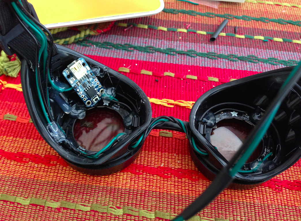
I chose black and green wires because I felt red would be too noticeable. I also routed the wires coming out of one nose hole and into the other nose hole so they hide behind the bridge of rubber holding the two halves together. You can barely see the black and green wires. Hot glue was used to hold the rings in three point AND two dots of hot glue held the Trinket at a slight angle in the left half of the goggle. Remember -- you're not wearing these over your eyes, so the Trinket isn't going to be seen by you or anyone else. Be careful with the hot glue... try to put it where the mounting holes are for the Trinket if possible to avoid getting it on any of the tiny components.
I used three thin black zip ties to create loops for the six wires (two each from the rings and the Trinket) to feed to the middle of the elastic band and then soldered to the two wires from the battery box that will hang on a string around my neck and hidden from view. I was VERY liberal with shrink tubing. Every 2-3" I'd put on a 1/2" length of black shrink tubing on the two longer wires going down to the battery box.
All finished!
After flipping on the power, the goggles worked. Woo Hoo! The only issue was I didn't care for the random sparks generated for 10 seconds and followed by loops of color for 10 seconds. The cycle went Red Sparks, Red Loops, Green Sparks, Green Loops, Blue Sparks, Blue Loops. I just want Green Loops for now, so I modified the program so it only does green loops. You can download that modified program here -- a comment is included on the line where you set the initial color with the hex code for both red and blue if you want to change the color.
The only thing that is left is to clean the lenses of hot glue and add either some vellum paper over the lenses to soften the LED shine... there's a glass shop near my house that I might pay a visit to see if they can just create me two 50mm frosted glass lenses that can be inserted by themselves to replace the two-layer glass pieces that come in the lenses. (The goggle lenses unscrew from the front, so it's easy to pull out the glass.)
I'm quite happy with the final results as you can see in the video below... any questions, just ask.
Funny enough, in one of the videos for Experiment 3 I complain about the neighbor's dog barking... and I only just realized as I was wrapping up shooting a few modified versions of the circuit on Page 18 that the dog was barking because of me!
Experiment 3
If you're wondering if Radio Shack carries a phototransistor, the answer is yes... but don't give up if they don't have it in the slide-out drawer that's got the word "phototransistor" in big bold letters. One of the employees looked in the drawer above that one and lo-and-behold... a single phototransistor for sale. Moral of the story: parts get moved or restocked incorrectly. Look around before giving up.
All the other components I had in my collection, minus a 33K resistor -- I just put two 15Ks in series and was able to get successful results. I did have the 10 microfarad and 0.01 microfarad capacitors but if you don't have these, you'll be happy to know that a VARIETY of values of capacitors will work in this circuit. Just make certain you've got them inserted correctly!
Of course, the first time I turned on the power I didn't get any response. I've learned over time that the first power up rarely works because I always *ALWAYS* wire something up incorrectly... even after I've double-checked against the schematic. I think I may the schematic version of dyslexia because after I get that initial failed power up, I always find the mistake. In this instance, I had pin 8 running to GND, not 5V. Take a look at the schematic and you'll see that Charles' is using the schematic method where a line crossing another line does NOT mean a connection. I saw a connection to GND. A single jumper wire moved to 5V and I was in business.
This phototransistor is very interesting, and I'm glad to see that upcoming experiments will continue to use it for a while. The concept that light (photons) can be used to control the flow of current brings to mind all sorts of fun projects.
I'm including a bunch of videos for Experiment 3 -- the only differences between them are the values of the inserted capacitors. In some instances, you get a high whine... in others a very low ticking sound.
These are always fun little circuits to build because they give you immediate feedback on the special components used (in this case, the phototransistor) and how they behave.
Now, back to that dog. As soon as I turned off the circuit, the dog stopped barking. Turn it on, the dog barks. I hope I wasn't causing him any pain or distress, but I can't stop laughing at how annoyed I was that he kept barking when I was shooting video... my fault, Nixon!
(Got a neighbor with a dog who also likes to play his music really loud? I can see this circuit turned on at 3am in the morning offering a small amount of satisfaction. Just kidding!)
A few odds and ends:
* I'll return to Experiment 2 once my shiny new analog gauges arrive.
* The Mintronics: Survival Pack shown in the video below is $25 (refills are $20). Interestingly enough, it has a 555, a 7805 voltage regulator, and a good mix of useful capacitors, but no 2N2222.
I should have Experiment 3 finished up tomorrow -- fingers crossed. And while I'm waiting on components to arrive, I decided to tackle a couple of small electronics projects. One is for my son (age 7) and the other is one I'm hoping to finish before my electronics camp begins on June 17.
The Solar Marble Machine from Solarbotics.com
The first project is a little baggie of parts I purchased at Maker Faire for my oldest boy from Solarbotics.com -- it's the Solar Powered Marble Machine. In a nutshell, a small motor drives a geared wheel (with holes for small ball bearings) round and round... ball bearings come out one at a time from the top, roll down the spiral ramp, and feed back into the geared wheel at the bottom. A small solar panel provides the juice so the machine can operate indefinitely when placed in direct sunlight.
Today my son and I sat down to build it. Let's just say the part of the project that involved the laser-cut wood pieces went smoothly... the small circuit board that needed soldering up did not. The little circuit board didn't have holes... instead, you soldered components to small copper pads. I'm not a great solderer to begin with, and this thing was just pure frustrating. The pads are tiny... very close together, and I probably should have purchased a tinier tip for my soldering rig. Instead, I dove in and quickly discovered how hard it is to solder small lead wires on capacitors and transistors to pads while trying to keep the tiny solder beads from touching. I failed often. Lots of desolder wick was used, but in the end I either burnt out a component due to too much heat from the iron OR I created a short somewhere that wasn't easily visible to the eye. Whatever the case, there was no power going to the motor. My son was not happy. Neither was I.
Failed to get the circuit board to provide power.
But you know what? Make: Electronics gave me enough hands-on practice building circuits and soldering and adding in switches and such... I just knew I could fix this thing. It might not run on solar power, but it was going to run on something! That's the thing -- I think a lot of people might get frustrated and toss the entire thing out, but all that was needed was tossing out the little circuit board and finding a way to provide power to the motor. Why not just add a single 1.5v battery and a small switch to the mix and give my son the ability to turn the Marble Machine on and off?
And that's what I did. It doesn't look as perfect as the solar powered version, but my version has character. (And it'll run on a cloudy day). It took me about 15 minutes to find a tiny switch, a small 1xAA battery holder, and my wire strippers. Ten minutes after that, I called out to my son to come take a look at the operational Marble Machine. It made his day, and his smile made mine.
After getting the Marble Machine working, I was pretty fired up and feeling confident!
One of the things I learned (and learned WELL) from my time working through the experiments in Make: Electronics was the value of wiring up and testing a circuit before implementing a more permanent solution such as putting everything in a case. It's so much easier to pull out what you believe to be a faulty transistor or LED from a breadboard than to try and cut one out of a soldered circuit that's tucked tightly into a small project box.
Over the years, I've been guilty of buying small electronics projects and jumping right in with the soldering iron. I don't know my ratio of successes to failures, but I'd be willing to bet that I ruined a lot of projects by just slapping everything together before testing all the components. I've made a promise to myself to avoid that kind of thing, and so that's why today I spent a good hour or so wiring up the Kaleidoscope Goggles' components with a breadboard and jumper wire.
The wiring isn't complicated, but imagine if one of the components was bad to begin with? The Trinket is $8, and each of the NeoPixel LED Rings is $10. It seemed wise to spend the time to just see if everything would work as desired.
Test wiring wasn't fun. I should probably investigate some better options to replace the small copper clips and jumper wires I used to connect all the components, but it did work. The frustration mainly came from wires popping out from under the clips. The Tinker (circuit board) also isn't designed to insert into a breadboard, so I angled it a bit so I could insert jumper wires through three specific holes (GND, Pwr, and Pin#0). The rest of the components -- battery box and two NeoPixel rings were a mix of jumper wire with clip and jumper wires sharing connectivity on the breadboard.
Yeah, it's not pretty. Not pretty at all. I tested each of the rings separately before connecting them together and powering them up. As the video below shows, the rings worked perfectly. I'll have to tinker with the program to change the brightness, speed, and color choices (it's all randomized right now) but that's got to be a cakewalk compared to test wiring these finicky items.
I hope you don't mind me interrupting the coverage of the Make: More Electronics experiments... these experiments are going to go a little slow based on my examination of later chapters. But hopefully with these side projects you'll see that I'm trying to take what I learn from the books and apply them elsewhere. I've got plenty of ideas for some new circuits of my own as I work through the book, so hopefully you'll enjoy them scattered in here and there as we move through the book.
[Note: Getting that tiny Trinket controller operational was another hour of troubleshooting -- the Adafruit forums were EXTREMELY helpful in helping me narrow down the problem I was having getting it to control the rings. This little device is amazing, and I've got a dozen ideas of my own for how I could use it. Check out the details here. I have no affiliation with Adafruit -- just really like many of their projects]
* I'm trying to avoid the inevitable "special trip" to Radio Shack that always seems to be necessary five minutes after you begin wiring up a circuit. It happens. You get into a circuit, you're close to finishing, and you discover you have the wrong component or you lack a key one. Sometimes the wrong component can still be substituted, but most of the time you want to try and have the correct one on hand just so you know you've done everything you can to ensure the success of an experiment.
Today, I've put in an order with Jameco for a substantial number of components that will get me up to Experiment 15. I haven't looked beyond Experiment 15 (in Appendix B) but I imagine there'll be a lot fewer parts to order as the experiment numbers creep higher based on what I'm seeing from Experiments 5 to 15... lots of repeated components. That's good.
Even better? The almost 40 components I ordered only added up to $17.33 not counting shipping. If you've got the time, pick the slowest boat shipping you can handle. Here's a list of the components I ordered that you can match up with Appendix B.
My first bulk component order for Make: More Electronics. Certainly not my last.
For this order, I didn't order just one of an item, even if it calls for just qty-1. At these prices, I'm grabbing two and sometimes more of an item because I know I'll eventually use them. In the case of the 555 chips, I have some on hand... somewhere... I just don't want to get a headache squinting to read the little doodads and it's easier to order a bunch now and start my New & Improved Electronics Organization Method rather than the three tubs of mixed up components I'm using now. I knew that not organizing them to begin with would come back to haunt me...
I chose Jameco for one reason... Mouser was out of the phototransistor and I didn't want to wait the estimated three weeks. Jameco had them in stock, I added 3 to the cart... and then just kept working my way through Appendix B. If I do find that I'm missing something after this package arrives, I have access to ACK Electronics here in Atlanta who usually has just about everything I need... but at a higher price and at a 20-minute drive. Hopefully I got everything with this order. Probably not.
* Why are you learning electronics? I can think of a dozen reasons, but a key one is that I want to be able to make special items and circuits rather than buy them pre-built/wired. I've got all sorts of ideas running through my head for fun and interesting circuits, and only after completing Make: Electronics did I have the confidence to just dive in and start breadboarding and making mistakes. When I see something fun to make, I don't want to worry that I lack the skills to solder it up or figure out the correct wiring after looking at the sketchy documentation. I can do it, and I've done it. Over the last few years, I've purchased a few items here and there that required me to make some jumps or assumptions regarding a schematic... amazingly, the knowledge I gained from Book 1 has allowed me to not only complete those iffy projects, but to understand exactly WHY they work.
I mention this only because I've had an amazing opportunity handed to me this summer -- a local school has asked me to teach a beginner electronics class for ages 8 to 12. This one week camp got 22 kids signed up, about 15 of them in just a few days. It filled up so fast, the school has asked me to teach a second camp later in the summer and I've got 5 signed up for that one... and hopefully it will reach the minimum (10) in the next few weeks for it to occur.
This isn't a theory class. Just about 90% of what these kids will be doing involves hands-on activities, some taken from Book 1. They'll learn about circuits and voltage, resistance, and current and plenty more... but my goal isn't to take them too deep on these subjects but instead get them to making things and hopefully light that fuse that will cause them to go home and ask their parents for more books, more kits, and more components to use (and probably destroy).
It's going to be a fun week, and I'll likely share some more here once that camp gets underway on June 16. (And posts for that week are likely to be few, so just be warned.)
On Day 1, I'm taking in a bunch of the special projects I've built over the last few years. My hope is to get those young eyes wide open and curious about how they can make these things. Right now, I'm putting together the little group of items you see below left so I can wear it as the kids come into the room on Day 1... think it'll grab their attention?
Let's get this right out -- Experiment 2 is a bit tedious, but it's definitely going to cement in your mind some basics about not just transistors but voltage and current in general. For Experiment 2, you're dealing with a fixed voltage -- 5V DC regulated. So if you haven't already got your 5V regulated power via a breadboard, you'll have to get that up and running before attempting Experiment 2.
Measuring Base Current
Besides regulated power, you'll also want to grab a 1M potentiometer, a 470 ohm resistor, and a 2N2222 transistor. If you do it my way (versus Charles' way), you'll also want a large mix of jumper wire, tiny gator clips, and a few other items I'll try and point out.
First, I didn't have the tiny little potentiometer shown in Figure 2-3 on page 9. Oh, how I wish I had. Instead, I had one that I *thought* was 1M but turned out to be about 1/4 of what I needed. Rather than drive to Radio Shack for a single component (although I have done it in the past), I recalled that I had a 1M hand-dialed potentiometer in my component collection... from way back in Book 1. It works, but as you can see from some careful examinations of my photos, it did require a number of jumper wires and tiny gator clips to keep everything together. A few times a wire would pop out, so trust me... grab a tiny potentiometer designed for insertion in your breadboard.
The initial 5 microamps dialed in.
Also, dialing in the larger pot was less than fun. It's extremely finicky. That said, once I would get the proper base current dialed in, I'd let it sit for 5-10 seconds to make sure there wasn't any fluctuation. And don't MOVE the potentiometer after dialing it in... even a subtle shift in its location would occasionally cause a 0.1 fluctuation. Once I figured this out, I used more jumper wires to extend the reach of the wires connected to the pot -- wires directly connected to the pot were wired into the breadboard so I didn't have to pull them out again... and then another jumper wire would go from that row (on the breadboard) to wherever I needed it. This eliminated my jostling of the potentiometer once I got into the pattern of shifting the various wires to measure current in microamps, milliamps, and also to measure the voltage. (More on measuring the voltage in a second.)
Once I got the experiment wired up and figure out the right pattern of shifting jumper wires between the various locations necessary to get the proper readings for the chart, everything went smooth. But it did take about 5-10 minutes for me to debug my breadboard. I don't care how comfortable you are at dealing with breadboards, you're still going to make errors in wiring. I did. A lot.
The initial milliamps reading settled at 0.82.
For example, look carefully at the two above photos for initial 5 microamps and initial 5 milliamps, and notice the very tiny red jumper wire in the first photo that connects from the Power column on the breadboard to the Collector of the transistor. See it? Took me 10 minutes to figure out it needed to be removed so the circuit matched up to the one shown in Figure 2.5. Once that wire came out, the readings began to flow.
My data -- yes, my handwriting isn't great.
As you'll see in the next photo, my readings for current into Base, current into Collector, and the Beta Value and Voltage between Emitter and Ground differed greatly from the book's values.
It's explained in the chapter, but in case you missed it... there are a number of factors involved here that include the quality of my meter, the variation in that single resistor value (after the experiment, I measured it and found it to be 460 ohms, not the 470 ohms specified... Charles' resistor was very likely a completely different value), and the variation of voltage being provided by my 5V regulated power. Let's not forget variations in the transistor chemistry as well as the conductivity of all those jumper wires I'm using. The point is... my values may be different, but I *understand* what the chapter is trying to teach me. Make sure you do, too... before moving on to the next experiment.
If you read the chapter in its entirety before actually attempting the experiment (and I read it twice!) you'll know that the last column in the table on page 10 asks you to measure the voltage between the Emitter and ground. You can set this up and take this measurement in parallel to taking a reading of the current into the collector (starting in Step 3) and save having to go back and recalibrating the base current for each step of 5 microamps... but it does require a second multimeter. Use some jumper wires inserted into the proper places on the breadboard and when you're measuring milliamps but before you shut it all down and reset for microamps, take a voltage reading.
Don't forget to measure your voltage.
Let's see... any more thoughts? Be sure to kill the power (5V) to the entire breadboard as you move back and forth between microamp and milliamp configuration. I forgot a few times, and thankfully I didn't burn out any components. Don't take that risk.
Oh, and you'll notice I skipped setting up for 35 and 40 microamp experiments... mainly because I had a 7 year old complaining I was wasting his summer vacation by not spending every waking minute with him. Feel free to go all the way to 40 microamps, but I was able to get enough valid readings to see the linear pattern in my data. I even plotted it in Excel for a nifty line chart. (I also plotted a graph with Base current versus Voltage between Emitter and GND.)
Hey, look! A (somewhat) straight line!
Another straight line! (Base current vs Voltage b/w Emitter and GND)
Back in the Experiment 1, I saved that transistor (the one that was possibly damaged) for use in Experiment 2. I'm not using it here, but I am saving it for my writeup for Experiment 2 Part 2 -- for that, I'm still waiting for two little gauges to arrive. They should be here by end of week, but if not I may jump ahead to Experiment 3. But I will come back for a revisit of Experiment 2.
That's it for right now. Again, if you've got a copy of Charles' book, Encyclopedia of Electronic Components Volume 1, now would be a great time to read through the chapter on transistors.
And last but not least, my summary video of Experiment 2 below...
 To reacquaint myself with the 555 behaviors, I wired up a circuit like the one in Figure 4-3 (page 23) and selected some capacitors and resistors that would give me a somewhat easy to monitor pulse length. Referring back to page 157 of Make: Electronics, there's a chart that provides both resistor values and capacitor values so you can fine tune the pulse length you desire. I chose 10 microfarad capacitor for pin 6 (R1) and 470k resistor for pin 7 (C1) on page 23 for an approximate pulse length of 5.2 seconds. The text tells you to use a 0.1 microfarad capacitor between pin 5 and GND. I put an LED into the mix along with a small On/Off button. To the right is a photo of my setup.